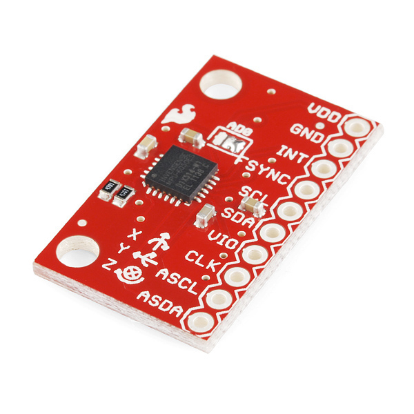
I splurged some hard-earned Amazon vouchers on toys this month, including a motion sensing break-out board from Sparkfun (via Proto-PIC in the UK).
The MPU-6050 chip is made by Invensense and its blurb says:
The MPU-6050 incorporates InvenSense’s MotionFusion™ and run-time calibration firmware that enables manufacturers to eliminate the costly and complex selection, qualification, and system level integration of discrete devices in motion-enabled products, and guarantees that sensor fusion algorithms and calibration procedures deliver optimal performance for consumers.Basically this means the chip has some fairly sophisticated processing on-board that handles things like sensor fusion. It does some useful stuff like calculating the overall direction of motion regardless of the chip's own rotation - this saves a lot of heavy floating-point calculations, which is good for integrating with Arduino and microcontroller systems. The accelerometer data can be read using an I2C bus (the linky is a library that builds on the Arduino Wire lib)
The breakout board is fairly simple to use - connect VDD to +3V3, GND to ground (duh) and the I2C pins (SDA and SCL) to the microcontroller I2C pins (A4 and A5 for most Arduinos/ATMEGA chips). The one 'gotcha' I found was that VIO needs to be connected to a reference voltage for the I2C logic to work... connecting this up to +3V3 seemed to work OK for me.
A note of caution - the chip is a 3V3 (3.3V) device so use a level shifter (or voltage divider) if using a 5V microcontroller... I'm using an Arduino mini pro 3V3 and a 3V3 FTDI USB to serial board for uploading sketches. Here's my test rig:
The rig is running off a LiPo battery on the right. The red board is the MPU-6050 accelerometer, the blue board is an Arduino Mini Pro and on the left is a graphical LCD from Adafruit (with a funky RGB backlight). The display is showing acceleration (in x, y and z) on the top row and rotation angle underneath. The circles show the amount of acceleration in each axis (bigger = more).
Software for the Arduino was acquired from here for the MPU-6050 and here for the graphical LCD . A few bodges and Pritstick code let me grab data from the MPU-6050 and push it onto the display. Note that the graphics code slows the whole system down to around 5-10 Hz. The serial only demos are much faster!
What next? Well, aside from building a balancing robot, I'm going to try to make an inertial navigation system... we'll see if its worth reporting on!


