Monday, 29 October 2012

Triple axis accelerometer and gyro - MPU-6050


I splurged some hard-earned Amazon vouchers on toys this month, including a motion sensing break-out board from Sparkfun (via Proto-PIC in the UK).

The MPU-6050 chip is made by Invensense and its blurb says:

The MPU-6050 incorporates InvenSense’s MotionFusion™ and run-time calibration firmware that enables manufacturers to eliminate the costly and complex selection, qualification, and system level integration of discrete devices in motion-enabled products, and guarantees that sensor fusion algorithms and calibration procedures deliver optimal performance for consumers.
Basically this means the chip has some fairly sophisticated processing on-board that handles things like sensor fusion. It does some useful stuff like calculating the overall direction of motion regardless of the chip's own rotation - this saves a lot of heavy floating-point calculations, which is good for integrating with Arduino and microcontroller systems. The accelerometer data can be read using an I2C bus (the linky is a library that builds on the Arduino Wire lib)
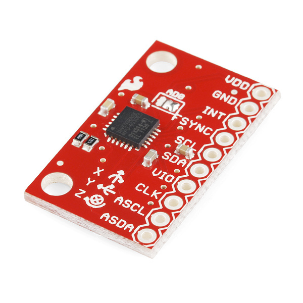
The breakout board is fairly simple to use - connect VDD to +3V3, GND to ground (duh) and the I2C pins (SDA and SCL) to the microcontroller I2C pins (A4 and A5 for most Arduinos/ATMEGA chips). The one 'gotcha' I found was that VIO needs to be connected to a reference voltage for the I2C logic to work... connecting this up to +3V3 seemed to work OK for me.

A note of caution - the chip is a 3V3 (3.3V) device so use a level shifter (or voltage divider) if using a 5V microcontroller... I'm using an Arduino mini pro 3V3 and a 3V3 FTDI USB to serial board for uploading sketches. Here's my test rig:


The rig is running off a LiPo battery on the right. The red board is the MPU-6050 accelerometer, the blue board is an Arduino Mini Pro and on the left is a graphical LCD from Adafruit (with a funky RGB backlight). The display is showing acceleration (in x, y and z) on the top row and rotation angle underneath. The circles show the amount of acceleration in each axis (bigger = more).

Software for the Arduino was acquired from here for the MPU-6050 and here for the graphical LCD . A few bodges and Pritstick code let me grab data from the MPU-6050 and push it onto the display. Note that the graphics code slows the whole system down to around 5-10 Hz. The serial only demos are much faster!


What next? Well, aside from building a balancing robot, I'm going to try to make an inertial navigation system... we'll see if its worth reporting on!




Thursday, 25 October 2012

Remote weather station using Raspberry Pi and Arduino

To make the weather station actually useful, the sensors need to go outside. Running a cable to the Raspberry Pi wasn't a good option, so I dug out a pair of XRF serial radio modules to handle sending the weather data over wireless.

An ATMEGA328 chip is used to run Arduino code that pulls raw data from the sensors and pushes the processed weather data over the serial radio link.


Outdoors module for the weather station

The ATMEGA chip sits on a custom board (actually its an Arduino shield prototyping board) that includes a power regulator for the 3V3 rail (for the XRF and sensors) and breaks out headers for the XRF module and sensors. At the moment its connected up with jumper cables, but the intent is to remote the sensors in a box that can have free air movement, whilst the processor, radio and battery sit in a snug, dry box.

The weather data comes from a BMP085 temperature and pressure sensor, a humidity sensor and a light-dependent resistor. More sensors (rain gauge, wind speed and direction) can be added with some code mods.

At the moment the system is mains powered; there is a battery holder for 1xAA rechargeable. The intent was to use a solar source to top up the battery and to use a buck booster to raise the 1.2V battery output to 5V for the ATMEGA chip. Battery life without solar top-up is around 5 hours... not good for the UK in winter! I'm using a low-power mode that only fires up the ATMEGA chip every 8 seconds (using the watchdog timer function) - the system waits 5 minutes between transmitting data. This is an attempt to eek out the power, but I think the honking 3V3 regulator and always-on-XRF are sapping the battery juice. I intend to play with a LiPo battery to see if we can get better performance... the original design intent allowed an output pin from the ATMEGA to drive the XRF such that it could be powered up only when needed to send data over the wireless.

Code to follow...


Tuesday, 25 September 2012

Live embedded Cosm graphs

As a minor bonus to the Cosm service, I found you can create an embeddable graph for your data to stick in any website...

Behold the current air pressure in Liss, live!

:)

Monday, 10 September 2012

Software Defined Radio hacks

The radio meteor project was great but has a few hang ups that are bugging me...

  1. The hand-held yupiteru radio has some issues with frequency stability that makes it difficult to work out what's a satellite and what's a glitch in the radio.
  2. The radio/soundcard interface seems to be susceptible to RF interference - eg from my computer monitor! This creates noise and false alarms on the meteor counter
  3. To detect meteors, my PC must be on and running the speclab software with the radio attached. This is tedious and uneconomical to run 24/7
  4. The feedline from the aerial to the radio is about 15m long. This may cause line losses (ie the signal gets weaker)
So to fix these I'm planning on using a digital tv USB dongle and an arduino to create a detector-in-a-box that could run off a low-wattage wall-wart and could dump data onto a USB stick or live stream over wired or wireless network onto the internet...


Fun, eh?

The system relies on a modern miracle chip built into some brands of USB digital TV dongles. The realtek Software Defined Radio (SDR) lets you tune into a huge range of frequencies (around 70MHz to 1.7 GHz). I got a generic one from Amazon for £17. There are a few sites around that list compatible dongles.

More to come on HDSDR and how to grab the data coming off the dongle...

Raspberry Pi as a Cosm data server

Part of concept I'm working up uses a base station to act as the bridge between a suite of sensors and the internet. Cosm is a web service that manages data upload, storage and retrieval and enables sharing of data streams.

Getting data off the Pi and into Cosm is reasonably trivial, but it took me a few tries to get it working, but here's the Cosm datastream. The Pi is hooked up to a BMP085, as described previously. In the end I bought an Adafruit cobbler for the convenience of hooking up to a breadboard and popped the Pi in a crust of laser-cut clear acrylic.

Tuesday, 4 September 2012

Raspberry Pi

Pi Power
After getting my Pi a few weeks back I've been struggling to get it further than the stock X windows GUI, let alone doing anything interesting with it. Part of the problem is having to dig out a PSU, keyboard and mouse and sitting in front of the telly with the Pi's composite out plugged into the TV AUX (all at a time when small people were cleared from the vicinity of the TV).

So I got the latest Occidentalis distro from the fantastic Adafruit Industries who built in a few handy utils and libraries (like SSH and libs to enable access to the GPIO pins). After a few test runs from the floor in front of the TV, I hooked the Pi up to my router with an ethernet cable and powered it up. Using SSH on my Linux netbook is straightforward, but you need extra software for Windows - PuTTY works well enough (although the connection has to be reset occasionally - not sure if this is the router, Pi or PuTTY...)

Next I got hold of my BMP085 pressure/temperature sensor breakout board, which uses the I2C bus to communicate with other devices. The Pi has built in I2C support brought out on the GPIO pins (one data and one clock pin for each I2C bus). Again, Adafruit have made a library and set of example programmes for interfacing with the BMP085 (amongst other things!). Connection to the GPIO pins at the mo is through an old IDE cable and hook-up wire. The Pi has 3.3V and 5V outputs right next to each other - so be careful connecting up 3.3V devices! Eventually I will make a breakout board, or buy one...

Currently I'm attempting to use Cosm to publish this data, but the examples in Python are defeating me at the moment.

Monday, 3 September 2012

New tabs

To try and organise my projects, I'm using the blogger 'pages' view. There are new tabs with an introduction and ongoing projects (here and here)