Monday, 31 December 2012

Quadcopter radio setup


My Spektrum DX6i receiver arrived this morning, which means I can test the quadcopter electronics :)


After some of the usual trial, error and Googling, I found the following process worked for getting my X600 quadcopter kit up and running:


X600-V3-COPTER-COMBO

 [SAFETY NOTE - do not put the propellors on!]

1. 'Bind' the RC transmitter and receiver (For Spektrum this requires a 'bind plug' that shorts the bind signal pin to its ground pin). Follow the bind instructions for your radio kit

2. Connect each ESC in turn directly to the receiver's throttle channel. Then follow section 2 of this guide:
- disconnect all ESCs from the board (only servo cables)
- connect ESCs one after the other directly to RX's throttle channel in order to proceed for calibration
- turn TX on
- move stick to full throttle
- Power the ESC
- wait for initialization beeps + 2 beeps
- after 2 beeps, move throttle stick to minimum
- wait for beeps (generaly 3 + 1 or 1 + 1)
- Unpower ESC and disconnect
- Repeat until all 4 are calibrated and you're done

Here's the ESC manual - there are a lot of poorly Englishised manuals in internet land :(


3.  Re-connect the KK multicopter board to the right ESCs (as in this guide)

4. Power up the quadcopter and 'arm' the KK multicopter board by holding the throttle/rudder stick down and right until the IMU board light comes on again - see chapter on 'Setting up the KKmulticontroller' of this guide

5. Go through the checks in the rest of the KKMulticontroller guide, testing that:
  • The throttle works
  • The pitch/roll/yaw commands are mapped correctly to elevator/aileron/rudder controls
  • The gyros work in the correct way (if you tip the quadcopter then the arm that is being dropped should rev up to stop the tipping motion - detecting yaw correction can be done similarly by twisting the quadcopter and noting if the front/back motors speed up or slow down.
UPDATE

Having wired up my quad in a 'plus' configuration (as advertised) I found that one of the arms didn't react properly. I also noticed that on dropping one arm two motors would speed up. This suggested that the KK multicontroller had an 'X' configuration loaded. To fix I had two options;
  1. Dig out an Arduino and flash it with the AVR ISP so I could compile and re-flash the KK multicopter ATMEGA168 with the quadcopter 'plus' config, or...
  2. Rebuild the 'copter in 'X' configuration.
I went with option 2 as less risky and simpler :) The new 'X' config seems to work in the correct way

Saturday, 29 December 2012

DIY CNC mill first 3-axis run drawing G-code from Inkscape


Quadcopter kit project

Santa pushed the boat out this year and, completely unprompted, gave me a quadcopter kit for Christmas :)

The kit included an airframe, battery, motors, propellors and motor control electronics. The airframe is a CSL X600

In the box were a load of bagged bolts, screws, aluminium section and cut glass-fibre board (?) and absolutely NO instructions.

I found a 'guide' here, a time lapse video here both of which helped to work out how this thing goes together as the design seems to have had some tweaks since the seller website was put up, so looking at the pictures there can be confusing.


The quadcopter is basically assembled in four parts:
1. The central chassis
2. The arms and motor mounts
3. The landing gear
4. Mounting the electronics and motors on the chassis and arms

I started with the central chassis and added the arms, working my way through the bits so I knew what fitted where. The process involved a bit of trial and a lot of error, but below is a pictorial build log...

This plate is the TOP of the quadcopter - here it is upside-down for fitting

Arms mounted

Arms - note that they have a top and bottom side. The tiny hole on the far right shows the bottom of the outer end of the arm - that hole is used by the tension spring in each landing leg


Folded arms

The bottom two plates - make sure that the arms can still fold once this plate is installed!

Motor mount and brushless motor

Motor fixing - use the round-head bolts supplied in the kit and ignore the counter-sunk screws that come with the motor

Landing gear - note this config looks different to the selling website pics

Landing gear spring

Landing gear in action

Out of all the bits supplied with the motor and prop, heres what I think you need...

Assembled prop

Finished build with electronics fitted


 Now to wait for a shiny new Spektrum radio set to arrive in the post...


Wednesday, 28 November 2012

Design for a robot vacuum

My dog makes lots of hair. Seriously, you can hoover the kitchen and five minutes later there's fluff all over. I want a robotic vacuum to keep it under control, but I'm not willing to spend £300+ on a roomba

So I'm going to build one.

Maybe.

First issue I can see is navigation - there are a lot of posts and designs that use ultrasonic sensors, IR, GPS :) and all kinds of expensive, fiddly kit that needs a hefty processor to calculate position ...

Well, my kitchen has a tiled floor. Surely I can use that grid for really simple navigation with no floating point maths or stats, all running on an 8-bit microcontroller of choice?

My intitial thoughts are:


Two bog-standard DC motors driving differential steering and forward/backward motion. This should allow the robot to swivel on the spot.

Three light sensors mounted on the underside of the robot will pick up the lines of the grout and determine if the robot is staying straight on the grid line, and detect when it crosses another line.

A bumper sensor (basically a switch) to detect when the robot hits an obstacle

Oh, and a modified hand-held hoover...

Possibly a charging dock also...


Sunday, 11 November 2012

Mantis-a-like CNC milling machine - update

I've been working on the Mantis CNC build recently to get the X-Y table up and running. Previously, I'd posted the design. I was working on a motor driver board based on an ATMEGA328P running the Arduino bootloader and three L293 motor driver chips. After a few months on-again-off-again (I/O pun) work on the board I gave up trying to get it working :( Instead I bought 3x Easy Driver boards.


These are really easy to use - just two pins are used to step the motor and tell it which direction to turn. They support bi-polar (4,6 and 8 wire steppers) motors and have a trim pot for varying the current supply.


So I wired an Easy Driver running on a PC PSU 12V supply into an Airpax stepper motor that I found a pair of on Ebay. It made a few noises and tick-tocked, but spectacularly failed to spin. I suspect these motors need more voltage/current to run. Oh well. In my box-o-junk I had a stepper from a 99p Ebay printer. Wiring that up and tweaking the step speed gave good results so I fitted this motor to the X-axis drive shaft on my mill. Now we're in business:


Monday, 29 October 2012

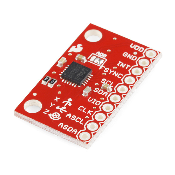
Triple axis accelerometer and gyro - MPU-6050


I splurged some hard-earned Amazon vouchers on toys this month, including a motion sensing break-out board from Sparkfun (via Proto-PIC in the UK).

The MPU-6050 chip is made by Invensense and its blurb says:

The MPU-6050 incorporates InvenSense’s MotionFusion™ and run-time calibration firmware that enables manufacturers to eliminate the costly and complex selection, qualification, and system level integration of discrete devices in motion-enabled products, and guarantees that sensor fusion algorithms and calibration procedures deliver optimal performance for consumers.
Basically this means the chip has some fairly sophisticated processing on-board that handles things like sensor fusion. It does some useful stuff like calculating the overall direction of motion regardless of the chip's own rotation - this saves a lot of heavy floating-point calculations, which is good for integrating with Arduino and microcontroller systems. The accelerometer data can be read using an I2C bus (the linky is a library that builds on the Arduino Wire lib)

The breakout board is fairly simple to use - connect VDD to +3V3, GND to ground (duh) and the I2C pins (SDA and SCL) to the microcontroller I2C pins (A4 and A5 for most Arduinos/ATMEGA chips). The one 'gotcha' I found was that VIO needs to be connected to a reference voltage for the I2C logic to work... connecting this up to +3V3 seemed to work OK for me.

A note of caution - the chip is a 3V3 (3.3V) device so use a level shifter (or voltage divider) if using a 5V microcontroller... I'm using an Arduino mini pro 3V3 and a 3V3 FTDI USB to serial board for uploading sketches. Here's my test rig:


The rig is running off a LiPo battery on the right. The red board is the MPU-6050 accelerometer, the blue board is an Arduino Mini Pro and on the left is a graphical LCD from Adafruit (with a funky RGB backlight). The display is showing acceleration (in x, y and z) on the top row and rotation angle underneath. The circles show the amount of acceleration in each axis (bigger = more).

Software for the Arduino was acquired from here for the MPU-6050 and here for the graphical LCD . A few bodges and Pritstick code let me grab data from the MPU-6050 and push it onto the display. Note that the graphics code slows the whole system down to around 5-10 Hz. The serial only demos are much faster!


What next? Well, aside from building a balancing robot, I'm going to try to make an inertial navigation system... we'll see if its worth reporting on!


Thursday, 25 October 2012

Remote weather station using Raspberry Pi and Arduino

To make the weather station actually useful, the sensors need to go outside. Running a cable to the Raspberry Pi wasn't a good option, so I dug out a pair of XRF serial radio modules to handle sending the weather data over wireless.

An ATMEGA328 chip is used to run Arduino code that pulls raw data from the sensors and pushes the processed weather data over the serial radio link.


Outdoors module for the weather station

The ATMEGA chip sits on a custom board (actually its an Arduino shield prototyping board) that includes a power regulator for the 3V3 rail (for the XRF and sensors) and breaks out headers for the XRF module and sensors. At the moment its connected up with jumper cables, but the intent is to remote the sensors in a box that can have free air movement, whilst the processor, radio and battery sit in a snug, dry box.

The weather data comes from a BMP085 temperature and pressure sensor, a humidity sensor and a light-dependent resistor. More sensors (rain gauge, wind speed and direction) can be added with some code mods.

At the moment the system is mains powered; there is a battery holder for 1xAA rechargeable. The intent was to use a solar source to top up the battery and to use a buck booster to raise the 1.2V battery output to 5V for the ATMEGA chip. Battery life without solar top-up is around 5 hours... not good for the UK in winter! I'm using a low-power mode that only fires up the ATMEGA chip every 8 seconds (using the watchdog timer function) - the system waits 5 minutes between transmitting data. This is an attempt to eek out the power, but I think the honking 3V3 regulator and always-on-XRF are sapping the battery juice. I intend to play with a LiPo battery to see if we can get better performance... the original design intent allowed an output pin from the ATMEGA to drive the XRF such that it could be powered up only when needed to send data over the wireless.

Code to follow...


Tuesday, 25 September 2012

Live embedded Cosm graphs

As a minor bonus to the Cosm service, I found you can create an embeddable graph for your data to stick in any website...

Behold the current air pressure in Liss, live!

:)

Monday, 10 September 2012

Software Defined Radio hacks

The radio meteor project was great but has a few hang ups that are bugging me...

  1. The hand-held yupiteru radio has some issues with frequency stability that makes it difficult to work out what's a satellite and what's a glitch in the radio.
  2. The radio/soundcard interface seems to be susceptible to RF interference - eg from my computer monitor! This creates noise and false alarms on the meteor counter
  3. To detect meteors, my PC must be on and running the speclab software with the radio attached. This is tedious and uneconomical to run 24/7
  4. The feedline from the aerial to the radio is about 15m long. This may cause line losses (ie the signal gets weaker)
So to fix these I'm planning on using a digital tv USB dongle and an arduino to create a detector-in-a-box that could run off a low-wattage wall-wart and could dump data onto a USB stick or live stream over wired or wireless network onto the internet...


Fun, eh?

The system relies on a modern miracle chip built into some brands of USB digital TV dongles. The realtek Software Defined Radio (SDR) lets you tune into a huge range of frequencies (around 70MHz to 1.7 GHz). I got a generic one from Amazon for £17. There are a few sites around that list compatible dongles.

More to come on HDSDR and how to grab the data coming off the dongle...

Raspberry Pi as a Cosm data server

Part of concept I'm working up uses a base station to act as the bridge between a suite of sensors and the internet. Cosm is a web service that manages data upload, storage and retrieval and enables sharing of data streams.

Getting data off the Pi and into Cosm is reasonably trivial, but it took me a few tries to get it working, but here's the Cosm datastream. The Pi is hooked up to a BMP085, as described previously. In the end I bought an Adafruit cobbler for the convenience of hooking up to a breadboard and popped the Pi in a crust of laser-cut clear acrylic.

Tuesday, 4 September 2012

Raspberry Pi

Pi Power
After getting my Pi a few weeks back I've been struggling to get it further than the stock X windows GUI, let alone doing anything interesting with it. Part of the problem is having to dig out a PSU, keyboard and mouse and sitting in front of the telly with the Pi's composite out plugged into the TV AUX (all at a time when small people were cleared from the vicinity of the TV).

So I got the latest Occidentalis distro from the fantastic Adafruit Industries who built in a few handy utils and libraries (like SSH and libs to enable access to the GPIO pins). After a few test runs from the floor in front of the TV, I hooked the Pi up to my router with an ethernet cable and powered it up. Using SSH on my Linux netbook is straightforward, but you need extra software for Windows - PuTTY works well enough (although the connection has to be reset occasionally - not sure if this is the router, Pi or PuTTY...)

Next I got hold of my BMP085 pressure/temperature sensor breakout board, which uses the I2C bus to communicate with other devices. The Pi has built in I2C support brought out on the GPIO pins (one data and one clock pin for each I2C bus). Again, Adafruit have made a library and set of example programmes for interfacing with the BMP085 (amongst other things!). Connection to the GPIO pins at the mo is through an old IDE cable and hook-up wire. The Pi has 3.3V and 5V outputs right next to each other - so be careful connecting up 3.3V devices! Eventually I will make a breakout board, or buy one...

Currently I'm attempting to use Cosm to publish this data, but the examples in Python are defeating me at the moment.

Monday, 3 September 2012

New tabs

To try and organise my projects, I'm using the blogger 'pages' view. There are new tabs with an introduction and ongoing projects (here and here)


Monday, 4 June 2012

Mantis-a-like CNC miller, build part 1

I'm going from fuzzy ideas and sketchup models to actual hardware now... After sourcing silver steel from these chaps in Wales (and most of the bolts, leadscrews, nuts and a few washers...) I grabbed a lump of MDF from Wickes and started building on Saturday...

The mutt is for appreciation of scale.


Saturday, 26 May 2012

DIY CNC milling machine

...or cartesian robot.

I've been researching building my own CNC mill for a few months now (read: trying to decide if its too much hassle to make my own or to save up £500-1000 and buy one...). In that time I've bought a few cheap stepper motors from Ebay and even a couple of 99p scanners and printers to disassemble for parts. I started putting together a motor driver board based on three L293D chips, an output multiplexer (need five digital lines per axis channel, three axis add up to 15 channels) and an ATMEGA328P (with Arduino bootloader etc)

I'm now at the stage where I need materials too build the system. This is the tricky bit as I don't have a workshop or any bench tools. So I looked around for DIY builds that were simple in their approach and that didn't need fancy machining or (too much/accurate) metal cutting.

Two options presented themselves:

Profile aluminium/aluminum section to create the frame (pros - easy to build up, Al is fairly easy to cut to size and drill and will provide a stiff frame. Cons - cost, once you add up all the section and fixtures. Difficulty making a cost effective linear slide without resorting to expensive rail-and-truck systems)

Wood (pros - really cheap, easy to cut, can glue, screw bolt or whatever suits. Cons - not as stiff, may deform over time, looks a bit rubbish)

A couple of example designs:

Aluminium section frame design with linear rails and trucks

Wood design using silver steel rods and Oilite bushes
After finding the mantis CNC machine design, I decided to go with wood and the desgin above.

A few design considerations:
  • The linear bearing is basically a pair of hardened, ground steel rods with Oilite (oil impregnated) bushes glued to a wooden truck. It would be really easy to misalign these rods and jam the axis movement.
  • Stiffness of the design is OK for a wood structure and the steel rods help to reinforce it, but there still may be a few mm flex, particularly on the y-axis (green truck)
  • The maximum cutting area is around 150mm in X by 225mm in Y by 75mm in Z. 
  • The end-mill motor will probably not be very powerful, but OK for milling copper clad board or wood. Hopefully it'll do aluminium as well :)
 Oh, a note on the steel rods - in the UK you can get something called 'silver steel' which is like 'tool steel' elsewhere. This stuff is intended for making tools (duh) and is fairly stiff. It is ground to a reasonable precision making it better than stock steel rod intended for machining to size. I hope.

First build update here


Sunday, 6 May 2012

Radio meteor detection

OK so its been a while since I posted up here...

I've been busy with work, children and other distractions resulting in a neglected blog :(

There are a few projects on the go at the moment, but I'm going to put up some details on detecting meteors using a PC sound card, a handheld radio scanner and some wires :)

The end results look a bit like this:


These screens are generated by SpecLab. The bright blobs on the top left are meteor trails. There is a great website here that explains what the blobs might mean. Basically, anything travelling left-right is showing a doppler shift (ie speeding up or more likely for a meteor - slowing down). Anything that appears in a vertical line is persistent over time. The vertical bands are radio interference (I think!) Occasionally there are tracks that might be satellites, but to be honest I don't really know!

More to come on how this was put together...