With expectations of at least breaking a prop and probably bending an arm, I took to the skies today with my X600 quadcopter...
The first flight was in a steady breeze on a local football pitch (soft muddy grass to cushion landings!) I fitted the props and tightened the bolts on the folding arms, plugged in the battery and took a deep breath as I armed the quadcopter from the transmitter.
From flying IR indoor helicopters I knew that a half-hearted throttle input would tip the machine, so I ran up the motors to idle, checked everything looked OK, then gave it some beans. The quad sprang up and almost hovered. I tried to correct for the wind drift and brought it down again in a controlled flop. Success! Nothing broken!
The next 30 minutes I got to grips with the controls. First impressions are that these machines need you to fly all four axis simultaneously. My experience with fixed wing aircraft wasn't much use as the quad could go in any direction equally fast. The immediate problem I had was I couldn't always tell which way was forward... pulling back on the stick to slow down may result in the quad going faster or sideslipping.
Next step will be to put something (lights? ball-and-string?) to show which way is 'forward' on the quad. Ultimately I'd like to implement and accelerometer based system to stabilise the quad and possibly do some control mixing to make it fly more like an aeroplane.
Saturday, 5 January 2013
Monday, 31 December 2012
Quadcopter radio setup
My Spektrum DX6i receiver arrived this morning, which means I can test the quadcopter electronics :)
After some of the usual trial, error and Googling, I found the following process worked for getting my X600 quadcopter kit up and running:
[SAFETY NOTE - do not put the propellors on!]
1. 'Bind' the RC transmitter and receiver (For Spektrum this requires a 'bind plug' that shorts the bind signal pin to its ground pin). Follow the bind instructions for your radio kit
2. Connect each ESC in turn directly to the receiver's throttle channel. Then follow section 2 of this guide:
- disconnect all ESCs from the board (only servo cables)
- connect ESCs one after the other directly to RX's throttle channel in order to proceed for calibration
- turn TX on
- move stick to full throttle
- Power the ESC
- wait for initialization beeps + 2 beeps
- after 2 beeps, move throttle stick to minimum
- wait for beeps (generaly 3 + 1 or 1 + 1)
- Unpower ESC and disconnect
- Repeat until all 4 are calibrated and you're done
Here's the ESC manual - there are a lot of poorly Englishised manuals in internet land :(
3. Re-connect the KK multicopter board to the right ESCs (as in this guide)
4. Power up the quadcopter and 'arm' the KK multicopter board by holding the throttle/rudder stick down and right until the IMU board light comes on again - see chapter on 'Setting up the KKmulticontroller' of this guide
5. Go through the checks in the rest of the KKMulticontroller guide, testing that:
- The throttle works
- The pitch/roll/yaw commands are mapped correctly to elevator/aileron/rudder controls
- The gyros work in the correct way (if you tip the quadcopter then the arm that is being dropped should rev up to stop the tipping motion - detecting yaw correction can be done similarly by twisting the quadcopter and noting if the front/back motors speed up or slow down.
Having wired up my quad in a 'plus' configuration (as advertised) I found that one of the arms didn't react properly. I also noticed that on dropping one arm two motors would speed up. This suggested that the KK multicontroller had an 'X' configuration loaded. To fix I had two options;
- Dig out an Arduino and flash it with the AVR ISP so I could compile and re-flash the KK multicopter ATMEGA168 with the quadcopter 'plus' config, or...
- Rebuild the 'copter in 'X' configuration.
Saturday, 29 December 2012
Quadcopter kit project
Santa pushed the boat out this year and, completely unprompted, gave me a quadcopter kit for Christmas :)
The kit included an airframe, battery, motors, propellors and motor control electronics. The airframe is a CSL X600
In the box were a load of bagged bolts, screws, aluminium section and cut glass-fibre board (?) and absolutely NO instructions.
I found a 'guide' here, a time lapse video here both of which helped to work out how this thing goes together as the design seems to have had some tweaks since the seller website was put up, so looking at the pictures there can be confusing.
The quadcopter is basically assembled in four parts:
1. The central chassis
2. The arms and motor mounts
3. The landing gear
4. Mounting the electronics and motors on the chassis and arms
I started with the central chassis and added the arms, working my way through the bits so I knew what fitted where. The process involved a bit of trial and a lot of error, but below is a pictorial build log...
Now to wait for a shiny new Spektrum radio set to arrive in the post...
The kit included an airframe, battery, motors, propellors and motor control electronics. The airframe is a CSL X600
In the box were a load of bagged bolts, screws, aluminium section and cut glass-fibre board (?) and absolutely NO instructions.
I found a 'guide' here, a time lapse video here both of which helped to work out how this thing goes together as the design seems to have had some tweaks since the seller website was put up, so looking at the pictures there can be confusing.
The quadcopter is basically assembled in four parts:
1. The central chassis
2. The arms and motor mounts
3. The landing gear
4. Mounting the electronics and motors on the chassis and arms
I started with the central chassis and added the arms, working my way through the bits so I knew what fitted where. The process involved a bit of trial and a lot of error, but below is a pictorial build log...
![]() |
| This plate is the TOP of the quadcopter - here it is upside-down for fitting |
![]() |
| Arms mounted |
![]() |
| Arms - note that they have a top and bottom side. The tiny hole on the far right shows the bottom of the outer end of the arm - that hole is used by the tension spring in each landing leg |
![]() |
| Folded arms |
![]() |
| The bottom two plates - make sure that the arms can still fold once this plate is installed! |
![]() |
| Motor mount and brushless motor |
![]() |
| Motor fixing - use the round-head bolts supplied in the kit and ignore the counter-sunk screws that come with the motor |
![]() |
| Landing gear - note this config looks different to the selling website pics |
![]() |
| Landing gear spring |
![]() |
| Landing gear in action |
![]() |
| Out of all the bits supplied with the motor and prop, heres what I think you need... |
![]() |
| Assembled prop |
![]() |
| Finished build with electronics fitted |
Now to wait for a shiny new Spektrum radio set to arrive in the post...
Wednesday, 28 November 2012
Design for a robot vacuum
My dog makes lots of hair. Seriously, you can hoover the kitchen and five minutes later there's fluff all over. I want a robotic vacuum to keep it under control, but I'm not willing to spend £300+ on a roomba
So I'm going to build one.
Maybe.
First issue I can see is navigation - there are a lot of posts and designs that use ultrasonic sensors, IR, GPS :) and all kinds of expensive, fiddly kit that needs a hefty processor to calculate position ...
Well, my kitchen has a tiled floor. Surely I can use that grid for really simple navigation with no floating point maths or stats, all running on an 8-bit microcontroller of choice?
My intitial thoughts are:
Two bog-standard DC motors driving differential steering and forward/backward motion. This should allow the robot to swivel on the spot.
Three light sensors mounted on the underside of the robot will pick up the lines of the grout and determine if the robot is staying straight on the grid line, and detect when it crosses another line.
A bumper sensor (basically a switch) to detect when the robot hits an obstacle
Oh, and a modified hand-held hoover...
Possibly a charging dock also...
So I'm going to build one.
Maybe.
First issue I can see is navigation - there are a lot of posts and designs that use ultrasonic sensors, IR, GPS :) and all kinds of expensive, fiddly kit that needs a hefty processor to calculate position ...
Well, my kitchen has a tiled floor. Surely I can use that grid for really simple navigation with no floating point maths or stats, all running on an 8-bit microcontroller of choice?
My intitial thoughts are:
Two bog-standard DC motors driving differential steering and forward/backward motion. This should allow the robot to swivel on the spot.
Three light sensors mounted on the underside of the robot will pick up the lines of the grout and determine if the robot is staying straight on the grid line, and detect when it crosses another line.
A bumper sensor (basically a switch) to detect when the robot hits an obstacle
Oh, and a modified hand-held hoover...
Possibly a charging dock also...
Sunday, 11 November 2012
Mantis-a-like CNC milling machine - update
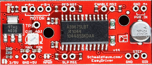
I've been working on the Mantis CNC build recently to get the X-Y table up and running. Previously, I'd posted the design. I was working on a motor driver board based on an ATMEGA328P running the Arduino bootloader and three L293 motor driver chips. After a few months on-again-off-again (I/O pun) work on the board I gave up trying to get it working :( Instead I bought 3x Easy Driver boards.
These are really easy to use - just two pins are used to step the motor and tell it which direction to turn. They support bi-polar (4,6 and 8 wire steppers) motors and have a trim pot for varying the current supply.
So I wired an Easy Driver running on a PC PSU 12V supply into an Airpax stepper motor that I found a pair of on Ebay. It made a few noises and tick-tocked, but spectacularly failed to spin. I suspect these motors need more voltage/current to run. Oh well. In my box-o-junk I had a stepper from a 99p Ebay printer. Wiring that up and tweaking the step speed gave good results so I fitted this motor to the X-axis drive shaft on my mill. Now we're in business:
These are really easy to use - just two pins are used to step the motor and tell it which direction to turn. They support bi-polar (4,6 and 8 wire steppers) motors and have a trim pot for varying the current supply.
So I wired an Easy Driver running on a PC PSU 12V supply into an Airpax stepper motor that I found a pair of on Ebay. It made a few noises and tick-tocked, but spectacularly failed to spin. I suspect these motors need more voltage/current to run. Oh well. In my box-o-junk I had a stepper from a 99p Ebay printer. Wiring that up and tweaking the step speed gave good results so I fitted this motor to the X-axis drive shaft on my mill. Now we're in business:
Monday, 29 October 2012
Triple axis accelerometer and gyro - MPU-6050
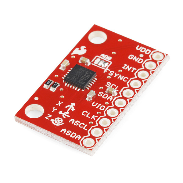
I splurged some hard-earned Amazon vouchers on toys this month, including a motion sensing break-out board from Sparkfun (via Proto-PIC in the UK).
The MPU-6050 chip is made by Invensense and its blurb says:
The MPU-6050 incorporates InvenSense’s MotionFusion™ and run-time calibration firmware that enables manufacturers to eliminate the costly and complex selection, qualification, and system level integration of discrete devices in motion-enabled products, and guarantees that sensor fusion algorithms and calibration procedures deliver optimal performance for consumers.Basically this means the chip has some fairly sophisticated processing on-board that handles things like sensor fusion. It does some useful stuff like calculating the overall direction of motion regardless of the chip's own rotation - this saves a lot of heavy floating-point calculations, which is good for integrating with Arduino and microcontroller systems. The accelerometer data can be read using an I2C bus (the linky is a library that builds on the Arduino Wire lib)
The breakout board is fairly simple to use - connect VDD to +3V3, GND to ground (duh) and the I2C pins (SDA and SCL) to the microcontroller I2C pins (A4 and A5 for most Arduinos/ATMEGA chips). The one 'gotcha' I found was that VIO needs to be connected to a reference voltage for the I2C logic to work... connecting this up to +3V3 seemed to work OK for me.
A note of caution - the chip is a 3V3 (3.3V) device so use a level shifter (or voltage divider) if using a 5V microcontroller... I'm using an Arduino mini pro 3V3 and a 3V3 FTDI USB to serial board for uploading sketches. Here's my test rig:
The rig is running off a LiPo battery on the right. The red board is the MPU-6050 accelerometer, the blue board is an Arduino Mini Pro and on the left is a graphical LCD from Adafruit (with a funky RGB backlight). The display is showing acceleration (in x, y and z) on the top row and rotation angle underneath. The circles show the amount of acceleration in each axis (bigger = more).
Software for the Arduino was acquired from here for the MPU-6050 and here for the graphical LCD . A few bodges and Pritstick code let me grab data from the MPU-6050 and push it onto the display. Note that the graphics code slows the whole system down to around 5-10 Hz. The serial only demos are much faster!
What next? Well, aside from building a balancing robot, I'm going to try to make an inertial navigation system... we'll see if its worth reporting on!
Subscribe to:
Posts (Atom)